Table of Contents
A water tank can be structurally sound and still create a serious operating problem when incoming water has nowhere safe to go. Poor water tank overflow design may flood a foundation, erode a slab edge, pull contaminated water back toward the tank, or hide a failed level control until the surrounding area is already wet. A defensible water tank overflow design makes the failure case and discharge route visible to every discipline.
This guide is for engineers, procurement teams, contractors, and plant operators who must define an overflow arrangement before an industrial or potable-water tank is fabricated. It explains the decisions behind practical water tank overflow design: the governing flow, the independent vent, the discharge location, sanitary protection, nozzle coordination, and the checks required before handover. Project specifications and local codes always govern; the purpose here is to help a buyer ask the right questions early.
Why Plan Water Tank Overflow Design Before Fabrication?
The overflow nozzle is often treated as a small accessory on a tank drawing. In practice, its elevation and location affect usable volume, roof or wall penetrations, external piping, access platforms, drainage, level alarms, and sometimes the foundation layout. A coordinated water tank overflow design prevents those interfaces from becoming late field changes. Changing any of them after panels or shells have been manufactured can add work and create avoidable sealing risks.
Good water tank overflow design starts with an operating scenario, not a nominal pipe size. Ask what happens if an inlet valve remains open, a level switch fails, two pumps run together, or a gravity supply continues flowing after the tank reaches its normal high level. The overflow route should deal with the credible maximum inflow without relying on an operator arriving at exactly the right moment.
For a broader procurement review, use the site’s industrial water tank manufacturer checklist alongside the water tank overflow design review. It helps align capacity, material, documentation, and installation responsibilities before a purchase order is released.
Separate the Overflow, Vent, and Drain
Three openings serve three different functions. The overflow removes excess water when the liquid reaches a defined level. The vent moves air as the water level rises and falls. The drain enables controlled emptying for cleaning, inspection, or repair. A documented water tank overflow design keeps these duties separate. Combining their functions makes water tank overflow design harder to verify and can leave the tank vulnerable during an abnormal event.
- The overflow protects against an overfill event and establishes the maximum uncontrolled water level.
- The vent limits pressure or vacuum as liquid enters or leaves the tank.
- The drain removes retained water under a planned, isolated operating procedure.
The Ontario Design Guidelines for Drinking-Water Systems explicitly state that an overflow pipe should not be considered a vent. EPA Region 8 guidance likewise describes dedicated vents, overflows, and drains for finished-water storage. These sources concern drinking-water systems, but the functional separation is also a useful review principle for many industrial tanks.
Define the Design Flow Before Sizing the Pipe
The first calculation input for water tank overflow design is the maximum credible filling rate, not the average daily consumption. Review every path that can fill the tank: duty pumps, standby pumps, gravity mains, transfer lines, recirculation returns, and temporary commissioning connections. Then define which sources could operate at the same time under a single control failure.
Record the flow basis in the design notes. Every water tank overflow design should be traceable to that basis. If the pump curve is available, use the flow the pump can actually deliver against the relevant system head rather than only the nameplate duty point. For a gravity-fed line, consider the available upstream head and the valve’s failure position. Where uncertainty remains, resolve it with the process or hydraulic designer instead of hiding it inside an arbitrary safety factor.
A complete water tank overflow design basis should identify the normal fill rate, the credible abnormal fill rate, the operating high level, the high-high alarm level, and the overflow weir or inlet elevation. These levels need enough separation to prevent routine level fluctuations or wave action from producing nuisance discharge.
Size the Complete Overflow Path, Not Only the Nozzle
A large nozzle does not guarantee adequate capacity. Water tank overflow design must account for the whole hydraulic path: entrance geometry, vertical and horizontal pipe runs, elbows, screens, flaps, reducers, air gaps, and the downstream channel or drain. A restrictive screen, long flat run, or partially submerged outlet can control the flow even when the wall penetration looks generous.
The sizing method should be appropriate to the arrangement. Depending on the geometry, the water tank overflow design may need an orifice, weir, open-channel, or partially full pipe calculation. Avoid assuming full-bore siphon flow unless the system is intentionally designed, vented, and analyzed to operate that way. The calculation should also check the water level required to develop the design discharge, because that level may be above the nominal overflow opening.
When a screen or mechanical exclusion device is required, include its clean and reasonably obstructed condition in the water tank overflow design review. A removable, accessible device is easier to inspect after an overflow than one buried inside a long pipe run.
Choose a Safe and Visible Discharge Point
The outlet should make an overflow visible without sending water toward the tank foundation, electrical equipment, pedestrian routes, chemical storage, or an unstable slope. Water tank overflow design is incomplete until the civil or site drainage system can accept the expected flow. The final water tank overflow design drawing should show where that water goes. A splash pad, tundish, open receptor, or graded drainage path may be appropriate, depending on the service and local requirements.
For potable-water service, avoid a direct physical connection to a sewer or contaminated drain. An air gap or another approved backflow-protection arrangement may be required. The EPA technical guidance on tank vents, drains, and overflows and the Ontario guidance both illustrate sanitary discharge principles for finished-water storage; the responsible designer must still apply the authority having jurisdiction for the actual project.
Keep the overflow separate from the maintenance drain unless the shared downstream system is deliberately sized and protected for both duties. The drain should be isolatable, while the overflow should remain available whenever the tank can receive water. This distinction is central to reliable water tank overflow design.
Coordinate Venting With Filling and Drawdown
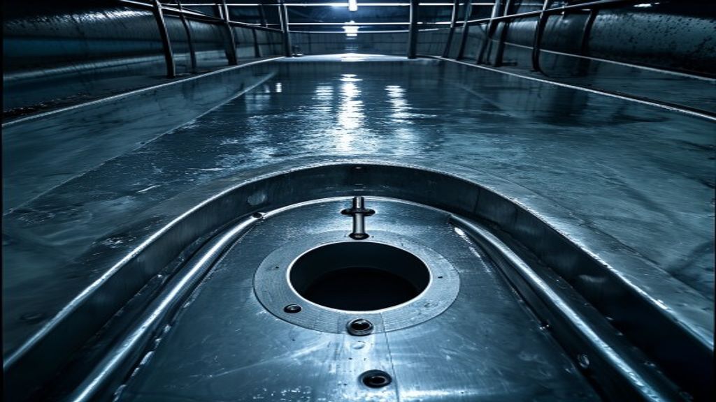
As water enters, air must leave. As water is withdrawn or drained, air must enter. A blocked or undersized vent can expose a tank to pressure or vacuum even when the overflow pipe itself is open. Therefore, water tank overflow design and vent design should be reviewed together but calculated for their separate duties.
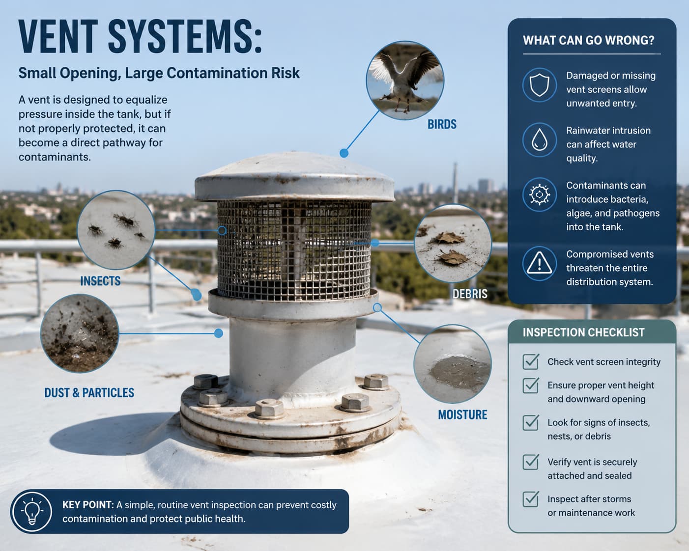
Check maximum filling, withdrawal, and drain-down rates, including rapid pump-out or emergency emptying. The water tank overflow design file should cross-reference the vent sizing basis. The vent termination should resist rain, debris, insects, birds, and deliberate contamination without creating excessive airflow resistance. If fine screening is specified, account for its pressure drop and maintenance condition. Thin-walled or sealed tanks may also need a correctly selected pressure-vacuum relief device based on the tank designer’s allowable limits.
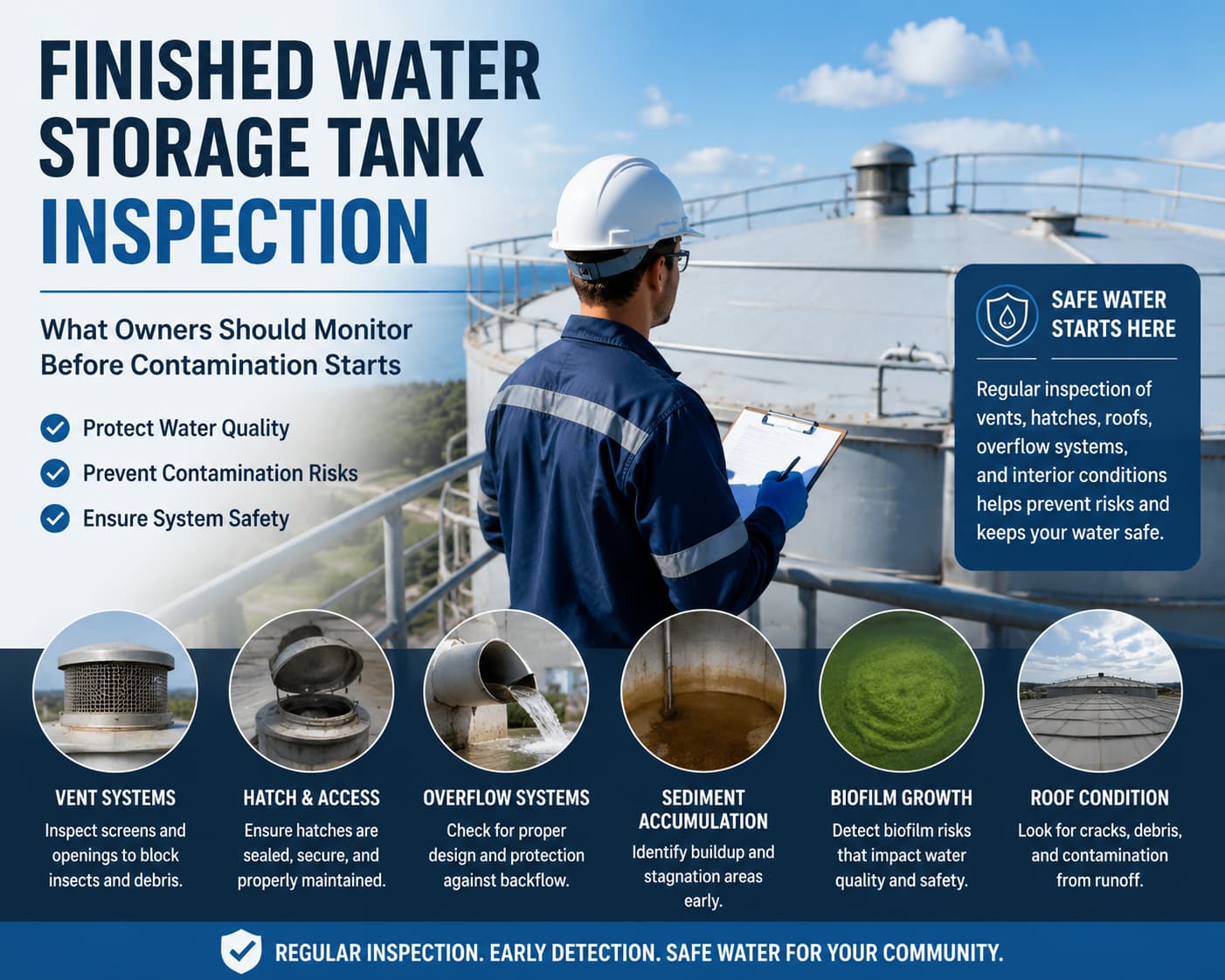
The site’s guide to finished water storage tank inspection shows why vents and overflows remain inspection points after commissioning. A strong water tank overflow design makes those components reachable without unsafe improvisation.
Protect Water Quality at Every Opening
Overflow and vent openings can become contamination pathways if they admit surface water, animals, insects, dust, or debris. Water tank overflow design for potable service usually requires sanitary terminations and compatible water-contact materials. The exact screen, flap, air-gap, and material requirements depend on local rules and the project specification.
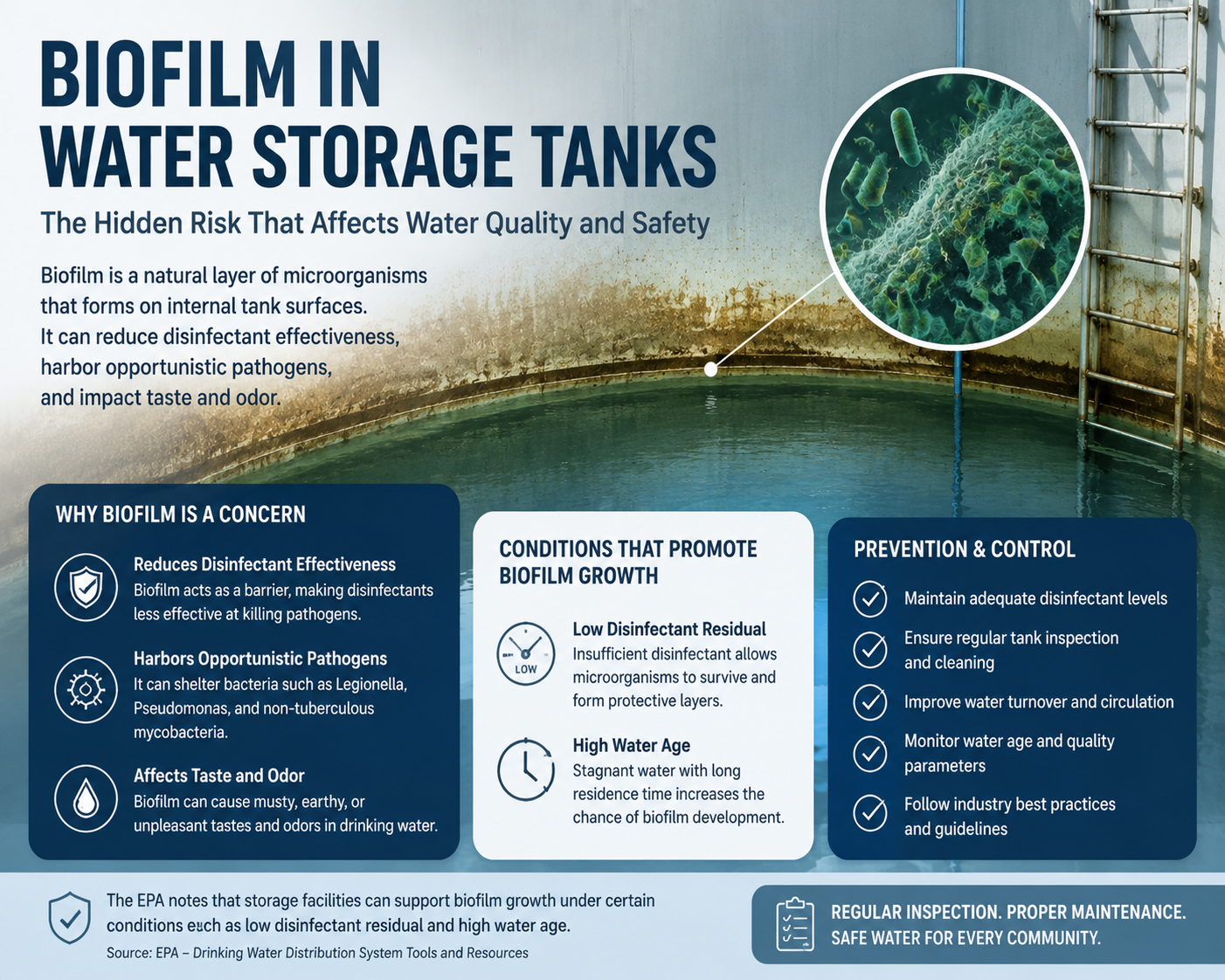
The NSF overview of NSF/ANSI/CAN 61 explains the health-effects scope for materials and components in contact with drinking water. Do not assume that one listed component makes an entire tank system certified. Confirm the required certification scope for coatings, sealants, gaskets, fittings, and other wetted parts. The related guide to potable-water tank gaskets and sealants can support that material review.
For non-potable process water, sanitary rules may differ, but water tank overflow design should still prevent rainwater entry, pest access, cross-connections, and uncontrolled discharge. Where the stored liquid can create an environmental or worker hazard, route the overflow into a contained and approved system designed for that service.
Coordinate Nozzles, Structure, and Maintenance Access
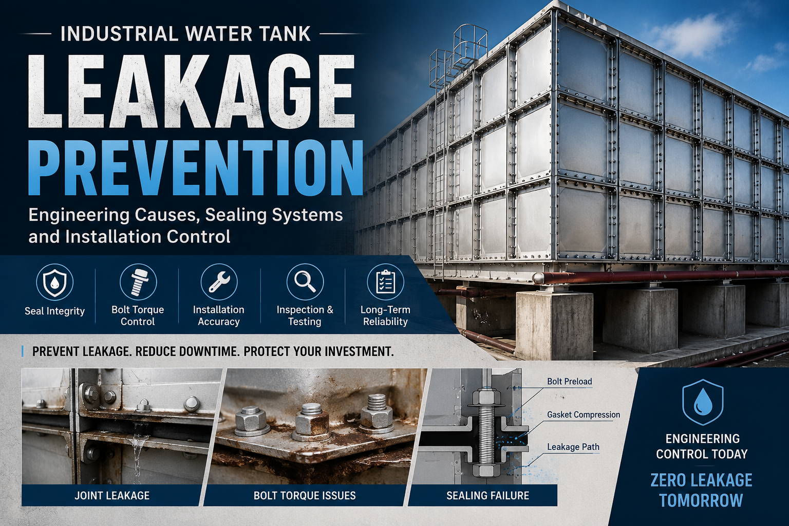
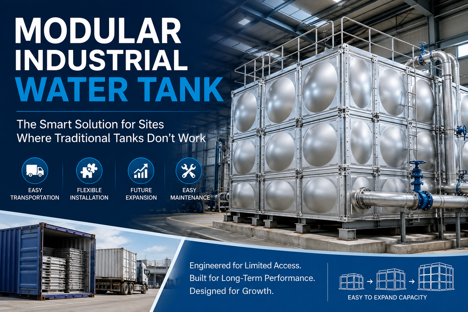
On bolted and modular tanks, nozzle positions must respect panel seams, bolts, stiffeners, roof supports, ladders, platforms, and foundation edges. Water tank overflow design should be shown on a coordinated nozzle schedule with centerline elevations, orientation, connection type, material, external load limits, and responsibility for attached piping.
External piping needs independent support so its weight, thermal movement, and vibration do not distort the tank connection. The water tank overflow design drawing should identify those support boundaries. Provide space to remove screens or flaps, observe discharge, and reach fasteners. If the overflow runs inside the tank, consider how it will be supported, inspected, and sealed at penetrations.
Coordinate these details before the drawings are approved. The industrial water tank installation guide explains the wider site, foundation, and assembly checks that should accompany water tank overflow design. Buyers comparing construction methods can also review the company’s modular water tank options.
Water Tank Overflow Design Review Table
| Review item | Question to answer | Evidence to retain |
|---|---|---|
| Maximum inflow | Which sources can fill the tank simultaneously during a credible failure? | Pump curves, gravity-head data, valve failure positions, and flow basis |
| Hydraulic capacity | Can the full route pass the design flow at an acceptable tank level? | Calculation covering fittings, screens, outlet condition, and downstream drainage |
| Vent duty | Can air enter and leave during maximum fill, drawdown, and drain-down? | Vent sizing basis and tank pressure or vacuum limits |
| Discharge point | Is discharge visible, protected from backflow, and directed away from hazards? | Site drainage drawing, elevation, air-gap detail, and civil approval |
| Water quality | Are openings and wetted materials suitable for the specified service? | Material schedule, sanitary details, and required certification records |
| Access | Can operators inspect and clean the termination safely? | General arrangement drawing and maintenance clearance review |
| Controls | Will independent alarms warn operators before sustained discharge? | Cause-and-effect schedule, alarm setpoints, and functional test record |
Use this table as a design-review prompt, not as a substitute for calculations. Each water tank overflow design decision should have an owner and a document that can be checked during drawing approval and commissioning.
What to Put in the RFQ and Drawings
A useful request for quotation gives the tank supplier enough information to coordinate the connection, while keeping the process designer responsible for the system-level hydraulic basis. Include the following water tank overflow design inputs:
- Stored liquid, operating temperature, and potable or process-water classification.
- Tank capacity, operating levels, alarm levels, and required overflow elevation.
- Normal and maximum credible fill rates, with simultaneous-flow assumptions.
- Preferred nozzle size, orientation, connection standard, and construction material.
- Internal or external overflow arrangement and required supports.
- Termination detail, screen or flap requirement, air gap, and receiving drainage point.
- Vent duty and any pressure-vacuum relief requirement.
- External pipe loads, insulation, heat tracing, and freeze-protection requirements.
- Inspection access, testing scope, documentation, and division of responsibilities.
Do not approve a general arrangement drawing that shows only a nozzle label. The water tank overflow design should be traceable from the operating scenario through the hydraulic route to the final discharge point. If project information changes, the affected calculation and drawing should be revised together.
Inspect and Commission the Complete System
Before filling the tank, verify that the overflow path is open, properly supported, correctly terminated, and free of construction debris. Compare the installation with the approved water tank overflow design. Confirm that the vent is installed and unobstructed. Check that valves have not been added to the overflow in a position where they can isolate the only overfill route.
Function-test the high and high-high level alarms, inlet shutoff logic, and pump controls. Where the commissioning plan permits a controlled flow test, observe the discharge route and check for leakage, foundation erosion, unsafe spray, or drainage backup. Record the as-built condition rather than assuming the installed system matches the approved water tank overflow design.
The EPA finished-water storage inspection checklist provides useful inspection prompts for public water systems. Any internal tank inspection must also follow the site’s hazard assessment and applicable confined-space rules. In the United States, OSHA 29 CFR 1910.146 addresses permit-required confined spaces in general industry.
Frequently Asked Questions
Can a tank overflow pipe be used as the vent?
It should not be treated as the dedicated vent. Water can block the overflow during the exact event when the tank still needs pressure relief, and sanitary devices or pipe geometry can restrict airflow. Provide and size the vent as a separate part of the tank system.
What flow rate should be used to size the overflow?
Use the maximum credible inflow that can occur during the defined failure scenario, including simultaneous sources where applicable. Average consumption is not an adequate basis for water tank overflow design.
Can the overflow connect directly to a sewer or storm drain?
Direct connections can create backflow or contamination risks and may be prohibited. Potable-water applications commonly require a visible discharge and an approved air gap or receptor. Follow the local plumbing, environmental, and water authority requirements for the project.
Should an overflow line have an isolation valve?
A valve that can close the only overflow path defeats the protection unless a specifically engineered alternative is available. If a valve is required for a special operating reason, the design team should assess locking, position monitoring, procedures, and redundant capacity.
Who is responsible for coordinating the overflow system?
The tank supplier normally needs to coordinate the nozzle and tank interface, while the process, mechanical, and civil designers define flow, attached piping, controls, and site drainage. The purchase documents should state these boundaries clearly so no part of the water tank overflow design is left between disciplines.
Final Design Takeaway
Reliable water tank overflow design connects five things: a credible inflow case, sufficient hydraulic capacity, independent venting, a protected and visible discharge point, and maintainable hardware. Define those items before fabrication, preserve them through installation, and verify them during commissioning.
If you are preparing a tank RFQ, send the stored liquid, capacity, operating levels, maximum filling rate, project location, and preferred connection details through the Zhengling contact page. That information gives the technical team a practical starting point for reviewing the tank interface and the required water tank overflow design inputs.