Managing a bulk liquid storage project means recognizing that the final verification phase carries the highest risk. Many site supervisors and quality control managers treat the final validation stage as a mere administrative formality. However, relying solely on basic pressure gauges without a systematic, engineered checklist often leads to catastrophic joint slippage, structural buckling, or structural failure upon full loading.
This technical guide eliminates the guesswork from your commissioning phase. By reading this guide, you will master the exact parameters required to execute a flawless tank hydrostatic test, learn how to manage controlled volumetric loading rates, and understand how to document a compliant inspection report that guarantees immediate engineering sign-off.
Оглавление
What is a Tank Hydrostatic Test?
A tank hydrostatic test is not just an oversized leak-checking routine. It is a rigorous, full-scale structural validation process where a newly constructed or repaired storage vessel is completely filled with water to test its mechanical integrity under maximum hydrostatic head pressure.
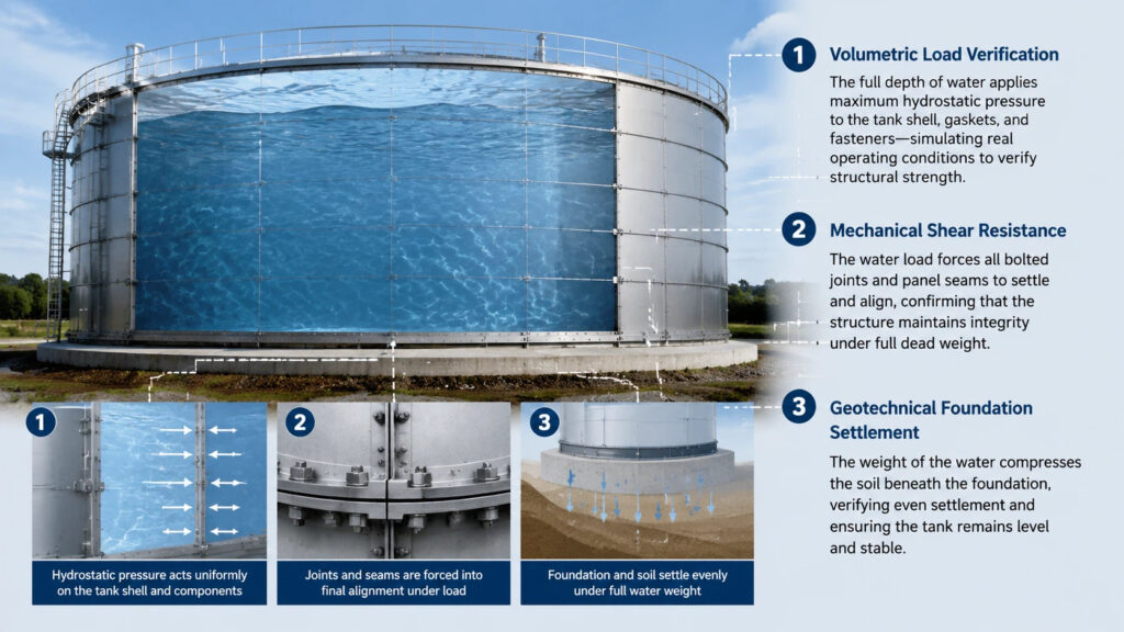
When evaluating liquid storage assets, this specialized testing regime serves three critical engineering functions:
- Volumetric Load Verification: It subjects the shell plates, synthetic gaskets, and structural fasteners to the exact design-density stresses they will encounter during decades of active operation.
- Mechanical Shear Resistance: For bolted configurations, the tank hydrostatic test forces the lap joints and panel seams to settle into their final mechanical alignment under full dead weight.
- Geotechnical Foundation Settlement: The massive weight of the water provides the only realistic method to compress the underlying soil, allowing engineers to verify that the concrete ring beam or gravel pad settles evenly without structural tilt.
Why Perform a Hydrostatic Test?
Skipping or rushing this validation phase creates severe liabilities for both the EPC contractor and the asset owner. Beyond the obvious goal of leak detection, running a comprehensive tank hydrostatic test is the ultimate proof of design accuracy before a tank goes live.
According to global engineering standards published by the American Water Works Association (AWWA), specifically the AWWA D103 standard for bolted steel tanks, structural components must be verified under full load before a certificate of occupancy is granted. A properly executed tank hydrostatic test mitigates the risk of catastrophic seam rupture, which can wash out adjacent infrastructure and trigger millions of dollars in environmental cleanup fines.
Furthermore, major industrial insurance underwriters will not issue operational asset coverage without a certified, third-party stamped report validating the tank hydrostatic test results. It serves as your definitive legal shield, proving that the asset was handed over in a completely stable, non-compromised mechanical state.
Standard Procedures for Testing Bolted Steel Резервуары для воды
Testing a bolted panel structure requires a highly specific approach compared to a traditional welded silo. Because bolted tanks rely on thousands of individual fasteners and compressed elastomeric strips, a hasty filling sequence will shear the vertical seams. You must follow a controlled, multi-phase execution roadmap.
Phase 1: Pre-Test Inspection & Bolting Torque Audits
Before a single drop of water enters the perimeter, the quality control team must perform a comprehensive structural audit.
1.Torque Verification: Use a calibrated digital torque wrench to cross-check a minimum of 10% of all structural panel bolts, ensuring they match the manufacturer’s exact foot-pound specification.
2.Debris Clearance: Sweep the interior floor clear of all construction debris, spare nuts, and sacrificial tools that could damage the floor liner or clog the drainage valves.
3.Nozzle Isolation: Blind off all process inlet and outlet nozzles using heavy-duty rated gaskets and blank flanges.
Phase 2: Controlled Volumetric Filling Rates
Never fill an industrial water storage asset at maximum pump capacity. Rapid filling traps air pockets and generates uneven localized stresses along the bottom chime angles.
- Initial Lift: Fill the first 1 meter of the tank extremely slowly—not exceeding a rate of 300 mm per hour. This seats the floor plates onto the foundation pad.
- Standard Lift Sequence: Once the initial lift passes a visual seam audit, increase the rate. However, maintain a strict limit of no more than 0.6 meters of vertical rise per hour, as outlined in structural commissioning guidelines.
- Intermittent Holding Windows: Pause the filling process at 25%, 50%, and 75% of total capacity. Hold the water level at each stage for 2 hours to conduct intermediate inspections of the panel overlaps.
Phase 3: The Stabilization and Holding Window
Once the water level reaches the maximum design liquid level, close the isolation valves. The official tank hydrostatic test countdown begins only after a mandatory 4-hour thermal stabilization window. This waiting period allows the water temperature to equalize with the ambient outdoor environment, preventing false pressure drops caused by thermal contraction. The tank must hold this full volume for a continuous period of no less than 24 hours.
Phase 4: Multi-Point Settlement Monitoring
While the structure holds full capacity, surveyors must monitor the foundation pad using high-precision digital levels.
- Take elevation readings at pre-marked benchmark lugs welded around the bottom ring beam parameter.
- Record measurements at the start of the hold window, at the 12-hour mark, and immediately before draining.
Safety Alert: If any single monitoring point shows sudden, uncoordinated soil compression (differential settlement exceeding project design tolerances), you must terminate the test and activate the emergency drainage protocol immediately.
Hydrostatic vs. Pneumatic Testing: Why Hydrostatic is the Gold Standard
In industrial engineering circles, substituting water with compressed air—known as pneumatic testing—remains a highly controversial topic. While air testing eliminates the need for post-test water disposal, applying pneumatic pressure to large-scale atmospheric structures represents an unacceptable safety gamble.
| Engineering Factor | Tank Hydrostatic Test | Pneumatic Testing |
| Stored Energy Medium | Water (Incompressible Fluid) | Compressed Air (Highly Compressible Gas) |
| Failure Risk Profile | Low. Localized tear results in a controlled wash-out. | Extreme. Structural failure causes an explosive blast wave. |
| Stress Distribution | Simulates true gravitational liquid payload payload accurately. | Uniform internal gas pressure; fails to simulate base loading. |
| Micro-Leak Sensitivity | High. Visible dampness or pooling forms at leak sites. | Moderate. Requires manual application of soapy bubble solutions. |
The physics of compressed gas storage explain why pneumatic testing is restricted to specialized high-pressure piping or small pressure vessels. Air compresses and stores massive kinetic energy. If a vertical seam on a bolted steel tank suffers a mechanical failure during a pneumatic test, the instantaneous release of that stored gas behaves exactly like an explosive detonation, tearing the steel shell into lethal shrapnel.
Conversely, water is virtually incompressible. A seam rupture during a properly managed water test results in a rapid drop in internal pressure and a localized stream of water, protecting the lives of your site operators. Therefore, utilizing a water-filled test method remains the undisputed gold standard for safety and regulatory approval.
Precision Leak Detection Technologies for Modern Commissioning
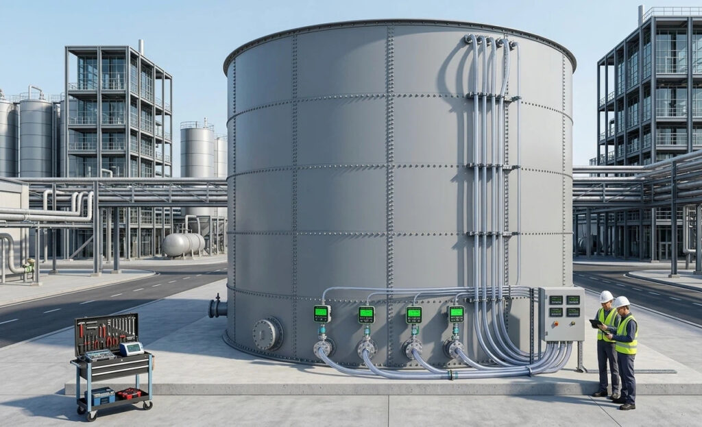
Modern industrial engineering has advanced far beyond simply walking around a tank shell looking for damp spots. To guarantee a zero-leak handover, field teams combine traditional visual observations with advanced diagnostic monitoring tools to optimize their leak detection workflows.
Acoustic Emission (AE) Testing
When a bolted joint experiences structural micro-slippage or a gasket undergoes a sub-millimeter failure under full hydrostatic load, it releases a minute burst of acoustic energy. By temporarily mounting acoustic emission sensors around the perimeter of the tank shell, technicians can pinpoint the exact coordinate of a structural anomaly without draining the asset.
Fluorescent Tracer Dyes
For projects involving ultra-pure process water or strict zero-tolerance containment mandates, technicians introduce non-toxic, highly concentrated fluorescent tracer dyes into the test water supply.
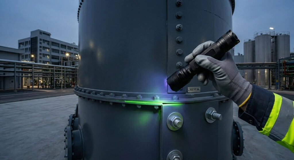
Once the tank reaches 100% capacity and the holding window concludes, inspection teams audit the external bolted seams at night using high-intensity ultraviolet (UV) inspection lamps. Any minor seepage that would normally evaporate instantly under sunlight leaves a glowing, unmistakable fluorescent trail on the edge of the steel panel.
Requirements for a Compliant Tank Hydrostatic Test Report
Your field testing process is only as good as your administrative documentation. To achieve immediate mechanical acceptance from project owners, municipal inspectors, and environmental protection agencies, your final requirements for tank hydrostatic test report documentation must be compiled into a structured engineering package.
Every compliant closeout dossier verifying the successful completion of the tank hydrostatic test must contain the following core datasets:
- Certified Calibration Logs: Signed certificates proving that all mechanical dial gauges, digital data loggers, and infrared temperature sensors used during the tank hydrostatic test were calibrated by an ISO/IEC 17025 accredited laboratory within 12 months of the test date.
- The Time-Velocity Filling Log: A continuous chronological record documenting the exact timestamp, current water elevation, and verified fill rate for every single stage of the loading process.
- Geotechnical Survey Datasets: The complete multi-point elevation ledger proving that foundation settlement remained uniform and within the structural boundary conditions set by the lead project engineer.
- Post-Test Water Disposal and Tank Cleaning Protocols: Documented proof showing that hundreds of tons of chlorinated or chemically treated test water were neutralized and discharged according to local environmental regulations, followed by a final tank sanitization log.
Navigating Post-Test Protocols and Risk Management
Completing the 24-hour hold window without a drop of water escaping is a major milestone, but the commissioning process is not quite finished. The manner in which you transition the asset from a static test state to an active operational state dictates the long-term reliability of the internal coating system.
First, implement a controlled drainage sequence. Just as rapid filling poses structural risks, draining a massive volume too quickly can generate an internal vacuum if the roof vents are blocked or undersized. Ensure all primary roof hatches are locked wide open before opening the main drain valves. Limit the discharge rate to match the maximum filling velocity to prevent sudden pressure differentials across the thin-gauge wall panels.
Second, initiate the definitive post-test water disposal and tank cleaning cycle immediately after emptying the vessel. Standing water left in the bottom sump or along panel crevices creates an ideal breeding ground for microbiologically influenced corrosion (MIC), which can compromise pristine steel surfaces in a matter of weeks. Thoroughly wash down the internal walls with clean, dechlorinated fresh water, inspect the internal sacrificial anodes or cathodic protection arrays, and deploy heavy-duty industrial air movers to completely dry the interior environment within 48 hours of test completion.
Заключение
Executing a rigorous tank hydrostatic test is the definitive line of demarcation between a volatile construction site and a certified, long-term industrial asset. Cutting corners during the pre-test torque audit, rushing the volumetric filling increments, or neglecting foundation settlement tracking puts your entire project timeline, capital allocation, and site safety at immediate risk.
By enforcing the structured roadmap detailed in this engineering guide, you ensure that your next bolted steel storage project transitions seamlessly from the commissioning phase to active, profitable operational service on the first attempt, backed by a flawless tank hydrostatic test record.
Часто задаваемые вопросы
What is the maximum allowable leakage rate for a bolted steel tank during a standard test?
Under the comprehensive framework of AWWA D103, a bolted steel tank is engineered to be completely watertight. There is zero allowable leakage rate during a tank hydrostatic test. Any visible weeping, running dampness, or active dripping at a bolted seam or nozzle connection constitutes an immediate test failure that must be mechanically resolved before final project sign-off.
Can we skip the 24-hour holding window if no leaks are detected within the first 4 hours of full loading?
Absolutely not. Structural steel panels and underlying structural foundations experience a phenomenon known as viscoelastic creep. It can take up to 12 hours under full gravitational load for soil matrices to compact or for structural fasteners to exhibit initial mechanical yielding. Cutting the hold window short invalidates the safety profile of the asset.
What should we do if an active leak is discovered while the tank is filled to 100% capacity?
Never attempt to tighten structural bolts or replace gaskets while a tank is under full hydrostatic pressure. Doing so introduces severe uneven stress concentrations that can cause catastrophic panel tearing. Mark the leak site with industrial paint, drain the water level down to at least 1 meter below the defect zone, and only then perform the necessary torque corrections or sealant applications.