A $100,000 chiller compressor dies prematurely on a commercial job site. The contractor blames the equipment manufacturer, but the real culprit is usually much simpler: a missing or improperly sized water tank in the piping loop. Without enough fluid volume to absorb thermal load shifts, the chiller short-cycles, destroying its own internal components.
Sizing and configuring industrial water tanks for HVAC systems is an exact science. Get the volume wrong, and you waste energy. Pick the wrong nozzle configuration, and air enters the chilled water loop, cavitating the pumps. This guide details exactly how to calculate capacity, select shell materials, and specify nozzle orientations to protect chillers and stabilize system temperatures.
Table of Contents
Why Do Chillers Short-Cycle? The Physics of a Thermal Buffer Tank for HVAC
Chillers have a minimum run-time requirement, typically dictated by the compressor manufacturer (often 5 to 10 minutes) to ensure proper oil return. If a building’s cooling load suddenly drops, the chilled water returns to the unit too cold, too fast. The chiller hits its setpoint and shuts off almost immediately. Minutes later, as the water warms, it kicks back on.
This rapid on/off switching is called short-cycling. It spikes power consumption and burns out compressor motors.
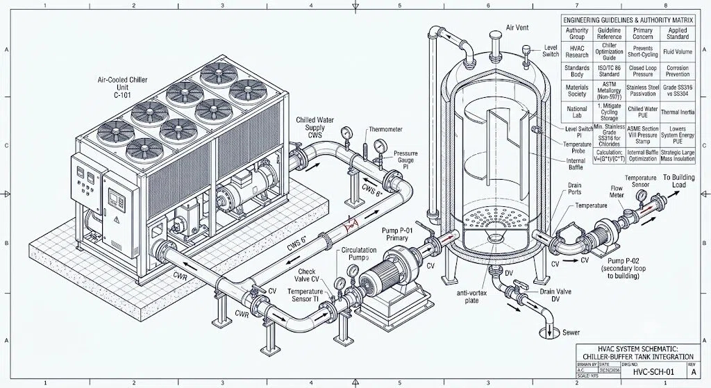
Installing a thermal buffer tank for HVAC artificially adds water volume to the system. This acts as a thermal battery (thermal inertia). The compressor now has to cool a massive block of water, ensuring it stays on long enough to complete a healthy mechanical cycle. According to a technical breakdown on compressor failures in The Air Conditioning, Heating and Refrigeration NEWS, lacking adequate system volume is the primary driver behind premature scroll and screw compressor death.
How to Calculate Buffer Tank Size for Chiller System?
Guessing tank capacity leads to either wasted space or inadequate protection. The capacity of a cooling system water tank must be calculated based on the chiller’s minimum cooling step, the allowable temperature deadband, and the existing pipe volume.
Use the standard industry formula:
- V: Required buffer tank volume (Gallons or Liters).
- Q: The chiller’s minimum cooling capacity at its lowest staging step (BTU/hr or kW).
- T: The manufacturer’s required minimum compressor run time (minutes).
- C: Specific heat capacity of the fluid (water or glycol mix).
- ΔT: The allowable temperature deadband (the difference between the cut-in and cut-out temperatures).
- Vsys: The existing fluid volume already in the building’s piping.
The thermodynamic calculations demand exact fluid constants. As detailed in the Flexiheat UK technical guide on chilled water buffer tank sizing, the calculation constants alter significantly depending on whether you are using pure water or an inhibitor mix. If you run a 30% propylene glycol mixture, the fluid’s specific heat capacity ($C$) drops, meaning your cooling system water tank must be scaled significantly larger than a pure water system to hold the same thermal inertia.
SS304 vs. SS316: Specifying a Stainless Steel HVAC Water Tank
When specifying a water tank for central air conditioning system applications, the material dictates the lifespan. Carbon steel is cheap but will rust quickly if the closed-loop water treatment fails. Stainless steel is the industry standard, but you must choose between grade 304 and 316.
- Type 304 Stainless Steel: Suitable for standard chilled water and heating hot water loops where municipal water is used and chemical inhibitors are strictly maintained.
- Type 316 Stainless Steel: Contains 2-3% molybdenum. If your HVAC loop uses cooling tower water, well water, or operates in a coastal environment where chloride exposure is possible, 316 is mandatory.
Chlorides attack the passivation layer of 304 stainless steel, causing rapid localized failure. As detailed in the Wikipedia engineering entry on Pitting Corrosion, chloride ions accumulate in microscopic surface defects, turning into hydrochloric acid and drilling straight through the metal shell. Upgrading to a stainless steel HVAC water tank made of 316L prevents this specific chemical attack.
Insulation Standards for Chilled Water Storage
An uninsulated steel tank holding 42°F (5.5°C) water in a warm mechanical room will sweat profusely. This condensation creates severe slipping hazards, rusts adjacent equipment, and represents massive energy loss. The chiller has to work harder just to overcome the ambient heat bleeding through the tank walls.
For proper chilled water storage, the tank must be factory-insulated.
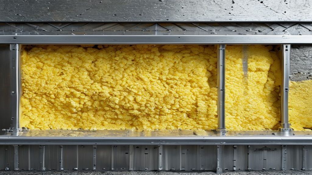
1.Closed-Cell Polyurethane Foam: 50mm to 100mm of injected, high-density polyurethane is required. It prevents thermal bridging completely.
2.Vapor Barrier: The insulation must be wrapped in a metal jacket (aluminum or galvanized steel) sealed with mastic. If water vapor penetrates the foam, it freezes or condenses against the steel tank, destroying the insulation value from the inside out.
The thermodynamic calculations demand exact fluid constants. As detailed in the live Flexiheat UK manual on chilled water buffer tank sizing, a system’s required thermal capacity scales drastically depending on whether the loop is filled with pure water or an inhibitor mix. When running a water-glycol mix of up to 50% in cold water loops, the fluid’s specific heat capacity drops, meaning your cooling system water tank must be scaled significantly larger than a pure water system to maintain identical thermal inertia and keep return temperatures stable
Baffles and Nozzles in an HVAC Water Tank
A tank is useless if the fluid dynamics inside are chaotic. When integrating a tank into a primary-secondary pumping system, how the water enters and exits is more important than the gross volume.
Stratification and Baffles
If hot return water mixes instantly with the stored cold water, you destroy the tank’s thermal capacity. Internal baffle plates physically force the water to take a longer path from the inlet to the outlet, preventing short-circuiting. This ensures the chilled water is drawn from the bottom, and the warmer return water stays at the top.
The Anti-Vortex Plate
When massive chilled water pumps draw from the bottom of an HVAC backup water storage tank, they create a suction vortex. Think of a tornado forming above a bathtub drain. If this vortex reaches the surface, the pump sucks in large amounts of air. This causes pump cavitation—literally blasting microscopic holes into the pump impeller.
Every bottom-outlet nozzle must be equipped with an internal anti-vortex plate. As discussed in a popular mechanical engineering thread on Reddit’s r/HVAC community regarding chilled water buffer tank sizing, neglecting the anti-vortex plate is a common mistake that leads to chronic air-locking in the top-floor fan coil units.
Mandatory Sensor Ports
Do not weld a tank without specifying:
- Thermowell Ports: Blind tubes extending into the tank where temperature sensors (RTDs) are inserted without breaching the water seal.
- Air Vent (Highest Point): To bleed trapped air during the initial fill.
- Drain Valve (Lowest Point): For heavy sludge removal and system flushing.
Chilled Water Expansion Tank Integration
A closed-loop HVAC system experiences thermal expansion. As the water warms, it expands; as it cools, it contracts. While the main buffer tank holds the working fluid, a separate chilled water expansion tank (usually a diaphragm or bladder tank) must be connected to the loop.
The expansion tank absorbs the pressure spikes. If you omit it, the expanding water will find the weakest point in the system—usually bursting a valve seal or cracking a heat exchanger. The expansion line should tie into the main system piping right before the primary pump suction, which is the point of no pressure change.
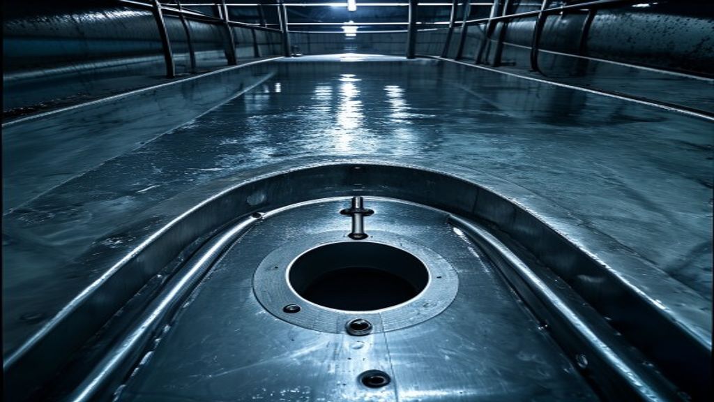
Securing the lifespan of expensive HVAC equipment comes down to fluid mechanics. By calculating the precise volume, insisting on an anti-vortex plate, and applying rigorous closed-cell insulation, industrial water tanks for HVAC systems transform from simple steel boxes into the most critical reliability component in your mechanical room. Before approving fabrication drawings, cross-check your specific heat calculations and verify the chloride levels of your local water supply to ensure your stainless steel selection will survive the next decade.
FAQ
What happens if my HVAC buffer tank is too small?
The system will short-cycle during low cooling loads. The compressor will turn on, satisfy the small volume of water rapidly, shut off, and turn right back on minutes later. This drastically reduces the lifespan of the chiller compressor.
Can a buffer tank replace a primary-secondary piping header (Decoupler)?
Yes. A buffer tank with four ports (two from the chiller, two to the building loop) naturally acts as a hydraulic separator (decoupler). It completely separates the pressure zones of the primary chiller pumps and the secondary building pumps while simultaneously adding thermal mass.
Does a chilled water buffer tank need to be ASME certified?
If the tank is operating under pressure in a closed-loop system (typically exceeding 15 PSI), commercial building codes usually require it to be built, inspected, and stamped according to ASME Section VIII Division 1 standards. Open atmospheric tanks do not require an ASME pressure stamp.
Where should the buffer tank be installed in the system?
For chilled water, it is standard practice to install the tank on the return line before the chiller. This gives the chiller a large, stable mass of mixed return water to cool, making temperature control much smoother.